Marcelo's new brake booster includes plenty of reservoir. Since he is retrofitting an electric wiper system, his Squarebird will have nothing else that runs on vacuum. Eric is right about not needing two check valves. Having more than one lowers the available vacuum.
To prove this out, simply remove the manifold check valve and run one vacuum hose to the booster. While the car is moving down a secluded road, shut off the engine and see how many brake pedal pumps it takes to stop. Now do the same test in your modern car.
Modern cars don't have 'extra' reservoirs because they are much more efficient than systems from the '50's. Modern systems also output my hundreds of pounds more assist. Marcelo's IS a modern system in every way.
I've been thinking about the space the old reservoir populates. It could be used for a new electric windshield washer reservoir. The new electric wiper switch already offers a contact closure when pressed in. That could energize a wash motor in a modern car reservoir. Bone yards throw them out daily. - Dave
-
NYsquarebird58's Brake System Overhaul and Disc Brake Conversion
I am not sure I understand the problem here, but I can tell you how Howard and I handled our disc brake conversion. If you have the under dash Kelsey-Hayes unit, leave it in place, including the connection to the reserve tank behind the inner fender. So we left the hose that was connected to that reserve tank hooked up, and are using it also. It has not caused either one of us any problems. If you don't have the under dash KH unit, and still have a hose going to a reserve tank behind that inner fender, I would continue to use it. If this is not what is being discussed, just disregard this...Leave a comment:
-
Will any vacuum reservoir tank do? I found this one on summit racing. Perhaps I can bypass the one that's hidden behind the fender and mount a smaller one under the hood, like the ones that hotrodders use when they're running big cams and power brakes.
http://www.summitracing.com/parts/MRG-3701/Leave a comment:
-
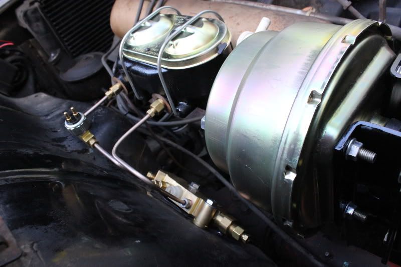
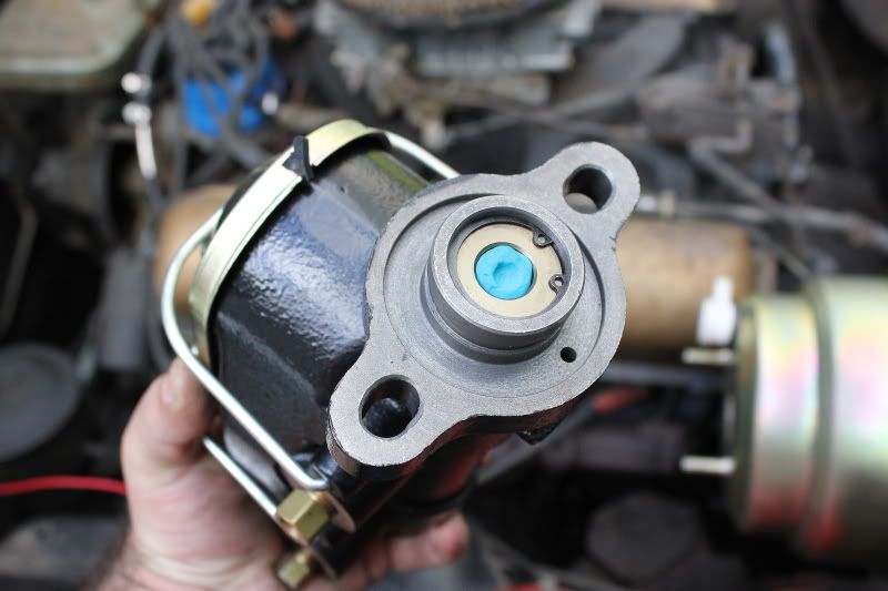
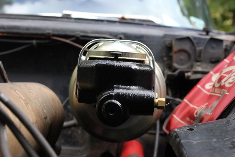
You've got the hard vacuum line coming out of the manifold - through the old right angle check valve - then it went to the "T" on top of the old booster. The line off the other side of the booster continued on to the reserve tank in the inner fender. You access the reserve tank by taking out the splash shield from inside the drivers side wheel well.
You "can" leave the reserve tank out but I don't think I would. It allows 2-3 additional power assisted stops should the engine quit and you are still rolling. After that it would just be like having non power assisted brakes - still work but more pedal pressure needed - a lot more.
Eric
this post has a pic of the tank but at the moment I can't find one with the tank installed location. (page1)
Leave a comment:
-
Eric, please point away! I'm figuring this all out as I go. What's this reserve tank you speak of? I was wondering where that vacuum line went after the "T" in the old booster. Do I still need it? Thanks for pointing out the check valve, I thought it was just an elbow.
Thanks!Leave a comment:
-
Oh yeah - super nice.
You probably have this all planned out but just noticed.......
The angle connector in your existing vac line is also a check valve. You now have a check valve in the new booster so don't think you'll need 2 - probably won't hurt having 2 though. (someone check me on that)
You will need a "T" connector to hook up the reserve tank behind the drivers side rear splash shield to your new booster since the built in "T" connector on the old booster went away. May be time to take out the reserve tank and check it for leaks (or better still - save that for a winter day).
Hope you don't mind me pointing things out - not trying to say you did anything wrong or junk like that - just trying to save you some time (and another trip to the parts store!).
I remember when I finally got mine to that stage - what a relief.
Looks really really good (hate to admit it but 10X better than mine). Those brackets you made are great.
EricLeave a comment:
-
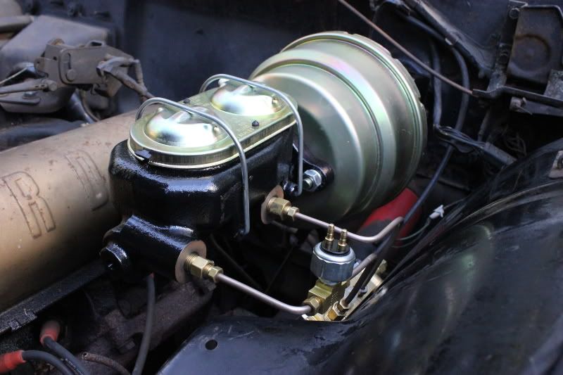
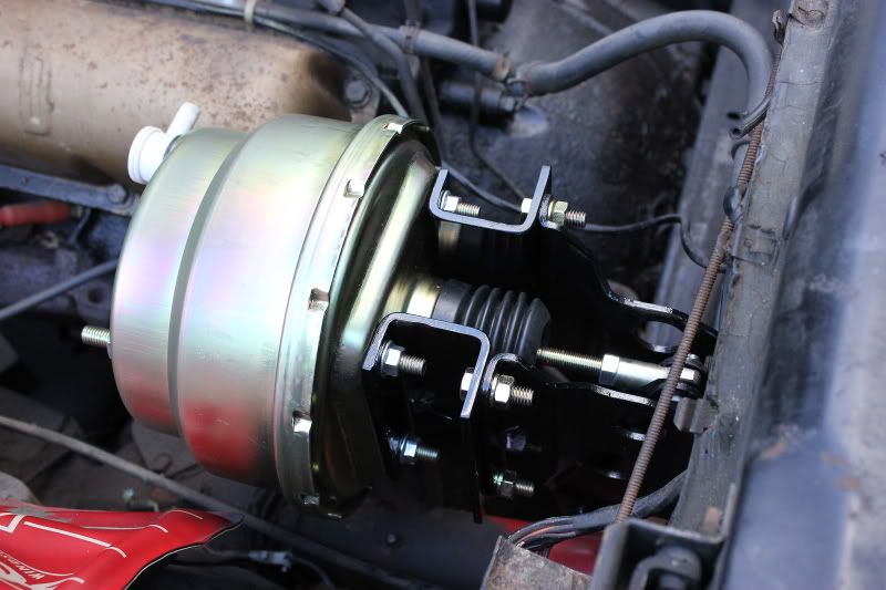
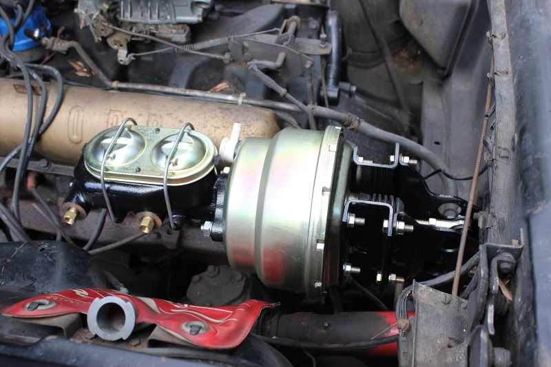
This setup is a huge, WOW! I love the space you maintained under the M/C for changing spark plugs. The bends look very professional and square. The Brake Switch is easy to change if necessary. This power brake system is very easy to maintain. Wait until you get the whole car plumbed. I wish I could be there to see your reaction the first time you step on that brake pedal.
Excellent job so far. - DaveLeave a comment:
-
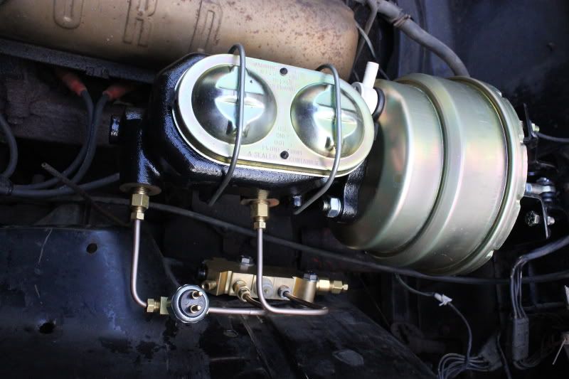
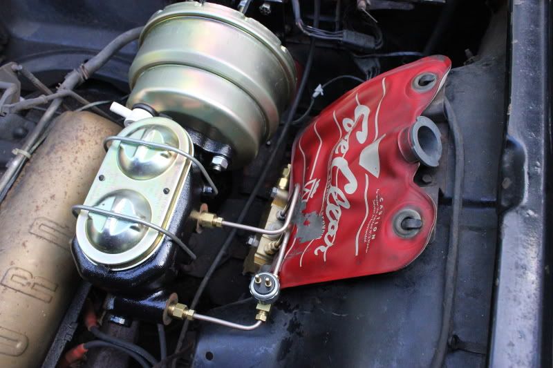
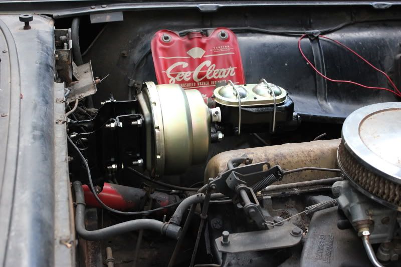
I didn�t get anywhere near as far along as I had hoped today, but I did manage to get the proportioning valve mounted and plumbed to the master cylinder,
I was originally going to mount the proportioning valve underneath the master cylinder, but I didn�t like how close it was to the exhaust manifold, so I decided on the inner fender just below the washer bag.
Leave a comment:
-
I hear ya'. I would have started a month sooner if it wasn't so humid or rainy around here. I've been lucky that the past two weekends have been just perfect.Leave a comment:
-
Looking really good. I am waiting for some cooler weather to get back to my disc conversion.Leave a comment:
-
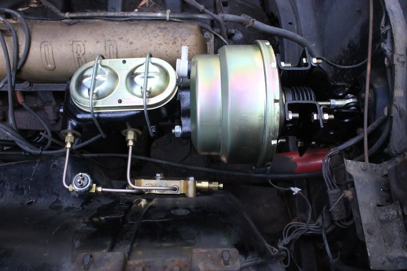
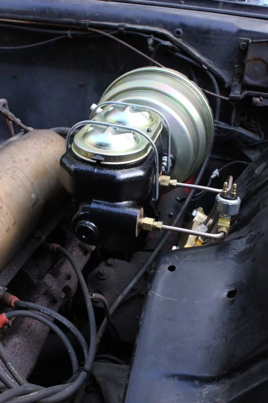
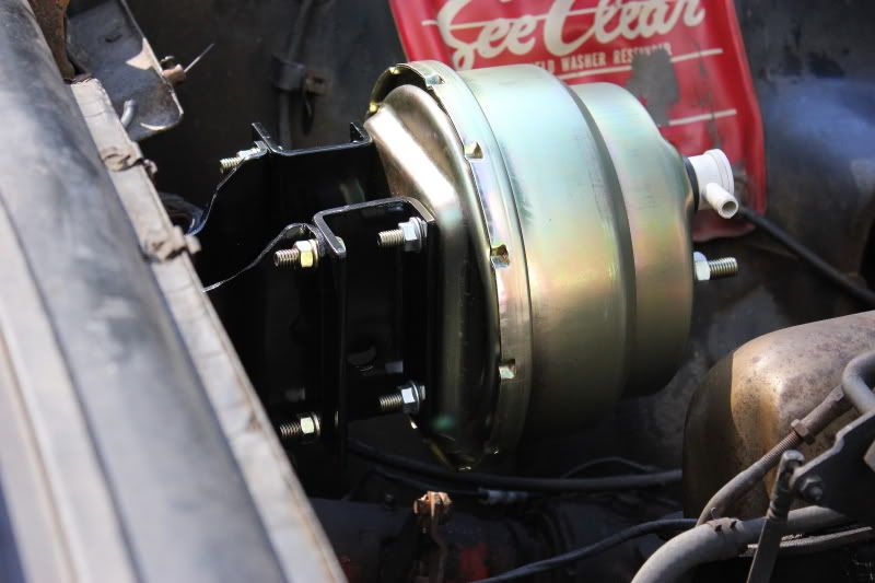
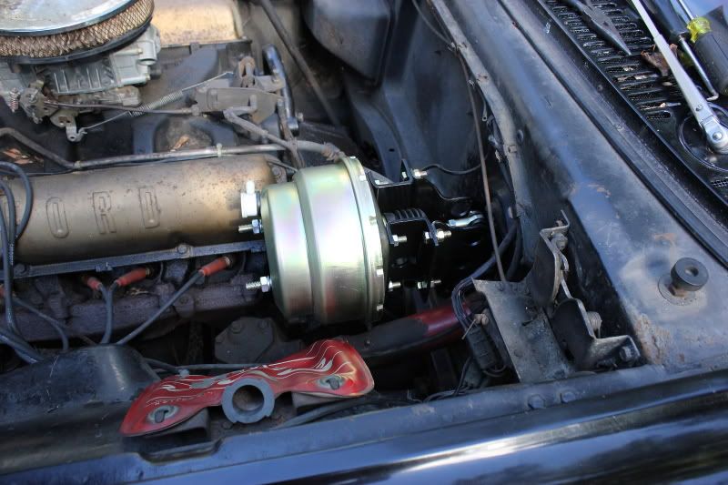
A little more progress today; I managed to get the booster and master cylinder all mounted up. Tomorrow I�ll bleed the master cylinder, mount the proportioning valve and start plumbing some hard lines.
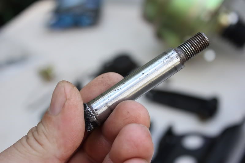
I was sure to lubricate all the clevis pins with some moly paste.
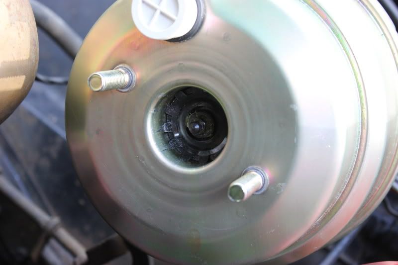
Here�s the clevis rod. I placed it in a vice and polished it with some sandpaper. After some lubrication, the clevis moves very easy.
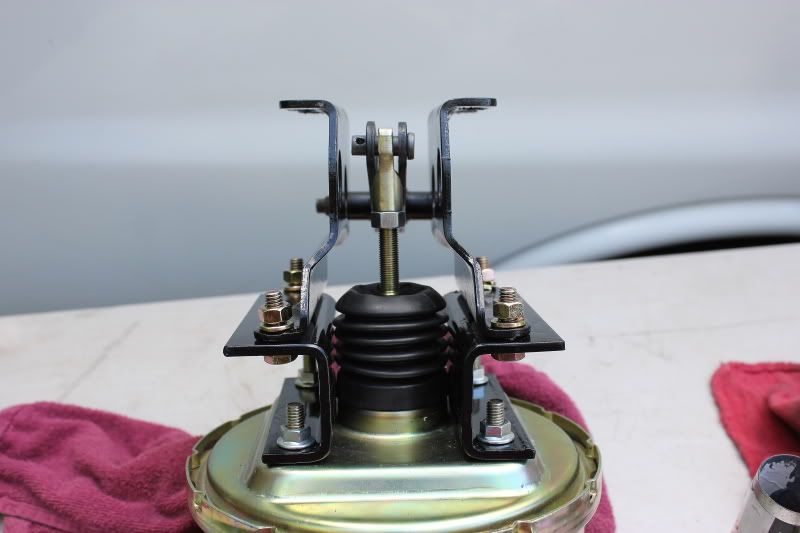
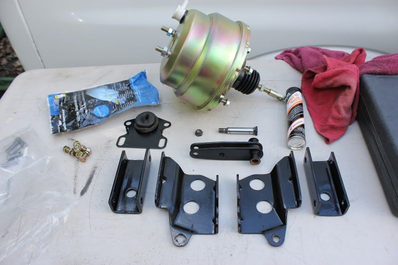
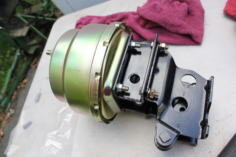
Here�s trailer bracket mounted between the booster and the Ford booster bracket.
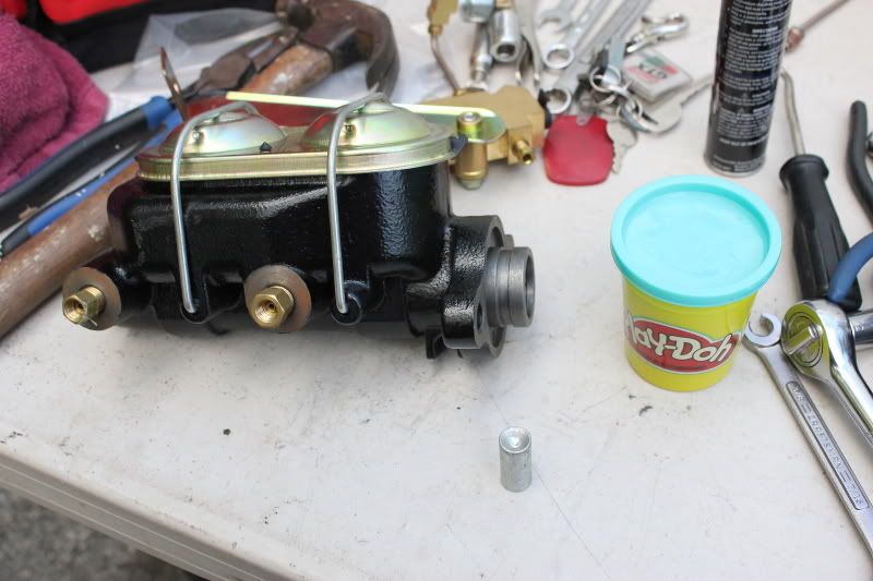
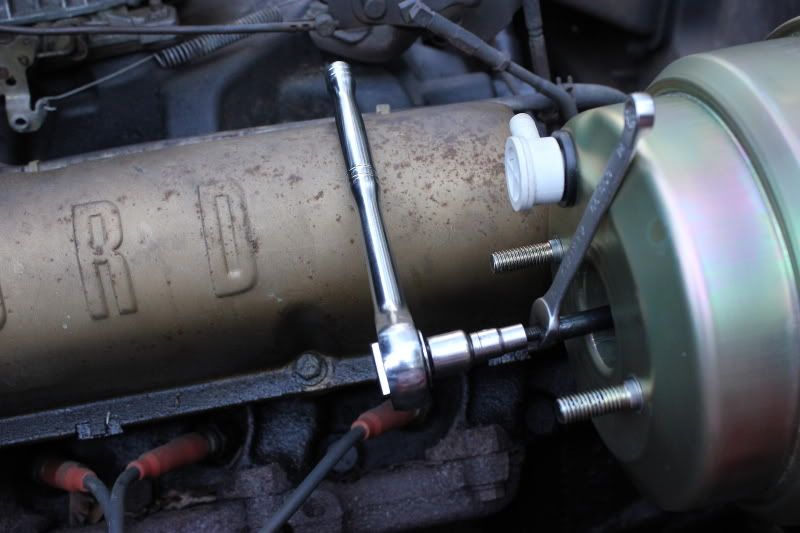
Time to adjust the jam nut on the end of the booster. I used some play dough on the end of the master cylinder�s push rod so that I can see the impression the jam nut leaves once the booster and master cylinder are sandwiched together..
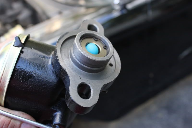

Notice the impression the jam nut left on the play dough. I just kept on backing that jam nut out until there was only a very thin skin of play dough between the jam nut and the master cylinder�s push rod.
I used a 6mm socket and a 7mm wrench to adjust the jam nut. (It also helped that I had my girlfriend hold the pedal down so that the jam nut was out in the open.)
Leave a comment:
-
-
Last week I mocked everything up using the jeep bracket. I felt that it pushed the whole setup out too far. The master cylinder was very close to the wheel well and the threaded rod coming out of the booster was to short to reach the brake pedal linkage. it could have definitely worked if I used a rod extension but it just seemed to hang out there too far for my liking.Leave a comment:
-
I do not understand why you would need to cut and weld the Jeep bracket. Mine works fine as is in mockup.Leave a comment:

Leave a comment: