
New Replacement Relay Conversion On a 1960 Thunderbird ~ Kevin Staton ~ shopguy
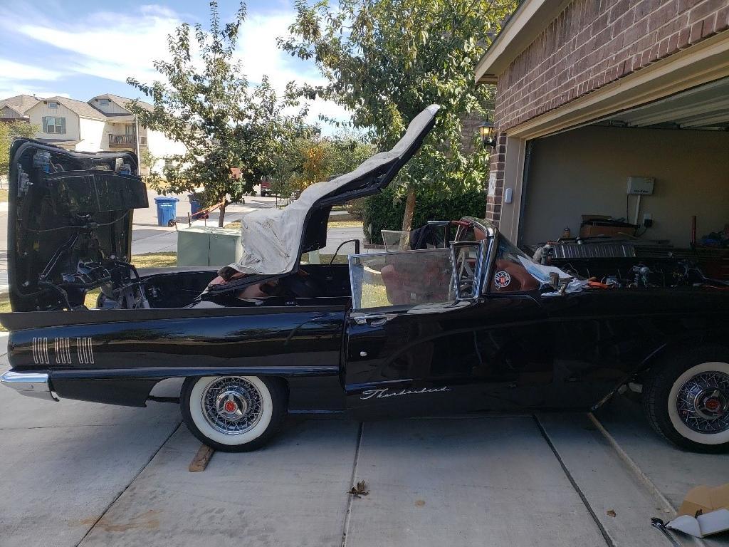
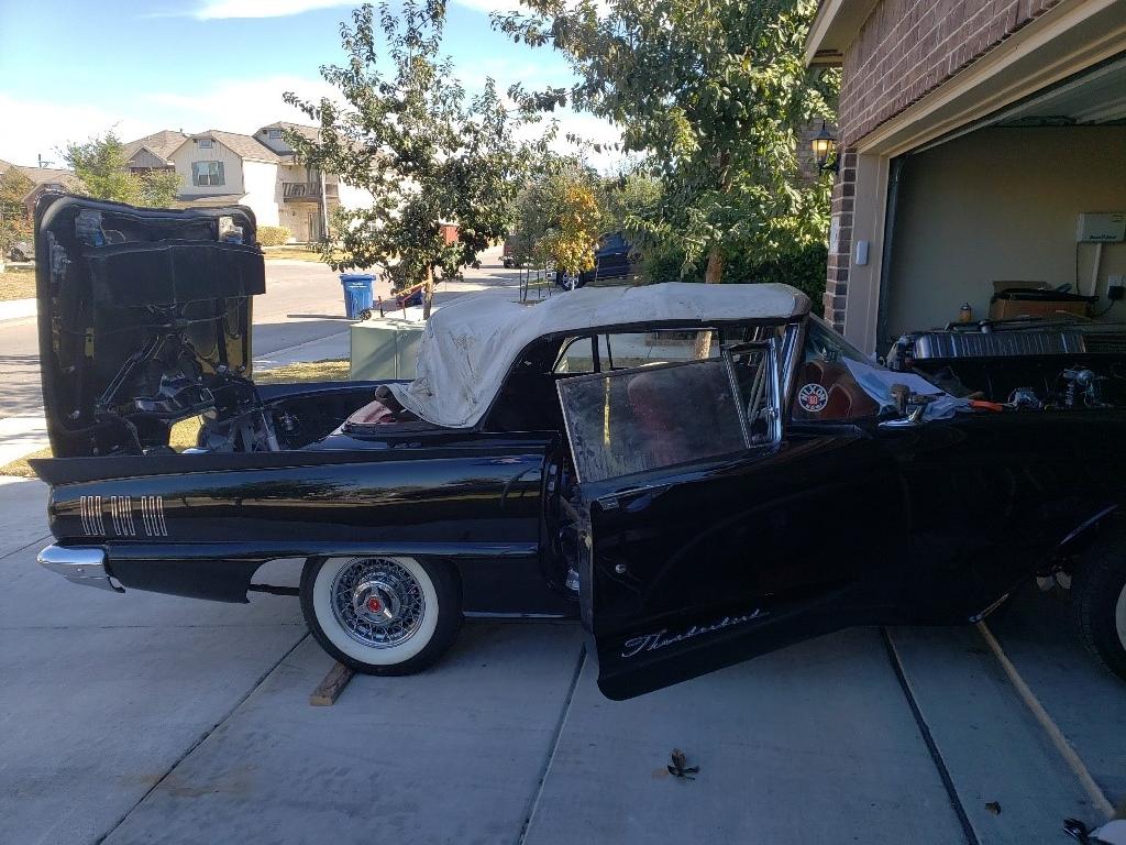
Those of you who are lucky enough to own a 1960-1966 Thunderbird convertible know that the way that the top mechanism functions is almost magical – when they work properly. When those antiquated relays start failing, it often causes the type of headache that a couple of aspirin simply won’t cure. Fortunately, John Draxler out of Pittsville, WI has been offering a modern electronic conversion to replace the original manual relays for many years now. This replacement relay system makes the top mechanism much more reliable, (like the car I am currently finishing). It also makes adjusting limit switches a breeze compared to the original set-up. Here are the steps I followed to revive and restore the top operation on Matt’s 1960 convertible:
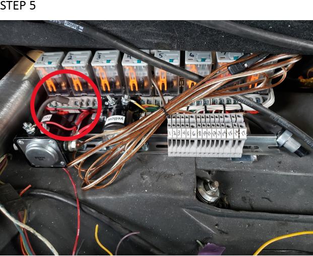
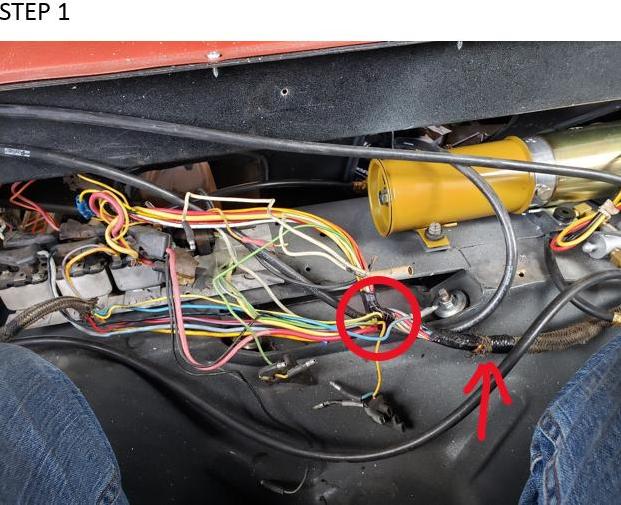 The first thing you want to do is tightly wrap some electrical tape around the wire harness (arrow) just beyond the Y (circle). You need to do this to be able to remove the extra wires that simply jump between the old relays.
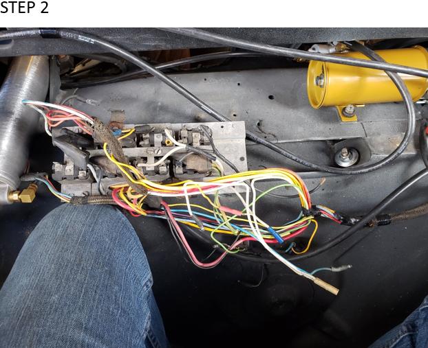 I then removed the relay pack to have a better view of what I had to work with. As you can see the harness I started with was a bit of a mess, but it was still useable.
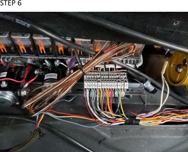
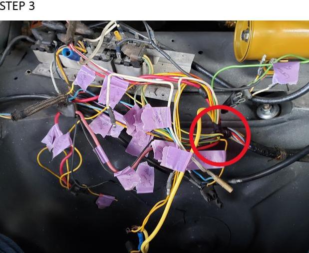 As I am a bit colorblind and as the wire colors are somewhat questionable after 60 years, I decided to label every wire. I labeled every single wire with its proper color as per the wiring diagram. This helped to ensure that there would be no question of each wires’ color. After I labeled each wire, I then cut all the wires free from the relay plugs and removed the final bit of tape holding the wires at the split (indicated in the circle). This allowed the extra wires that only jumped between relays to fall free leaving just the wires needed to attach to the new board.
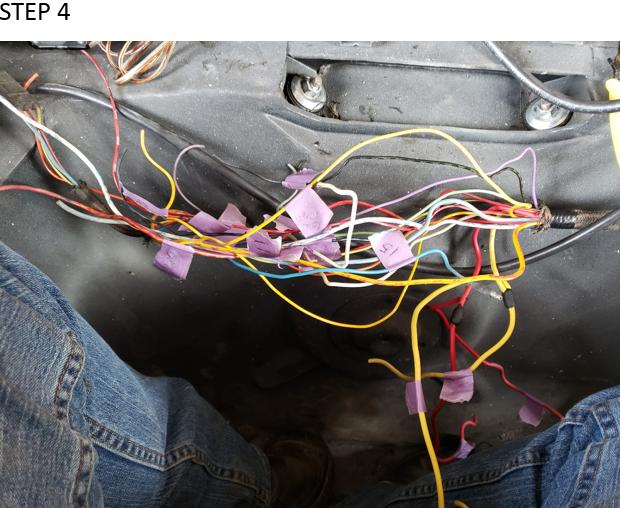 Next, I used the wiring diagram that came with the Convertible Relay Replacement System and marked the remaining wires with the newly assigned location on the new relay pack. The worst part is over, and you can now breathe again.
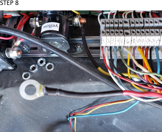
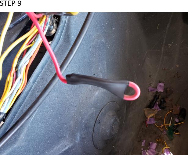
 I now installed the new relay unit and took each wire, one at a time, starting with number 16 and trimmed it down to be more manageable, stripped it and inserted it in its new location. NOTE: Wait to cut it to the proper length until after you have tested the system; I didn’t start with number 17 because that’s the main power wire (indicated inside of the circle) and it won’t reach without a modification.
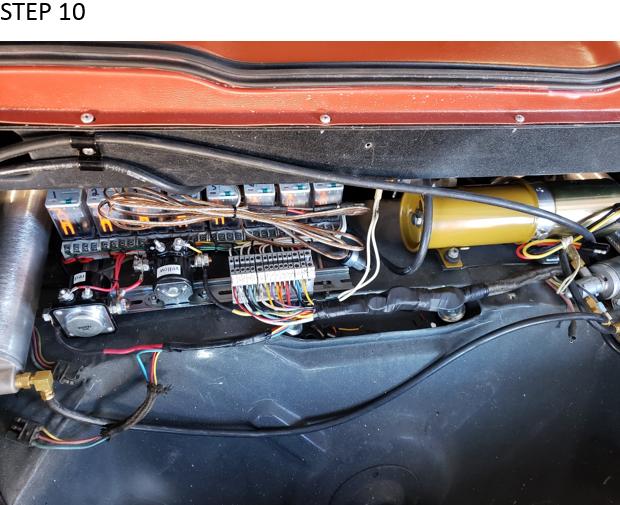
 This is an image of all the smaller wires installed. I will still need to install the black main power, plus the big yellow and red wires to the labeled relays.
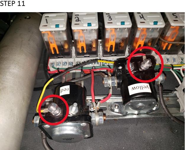
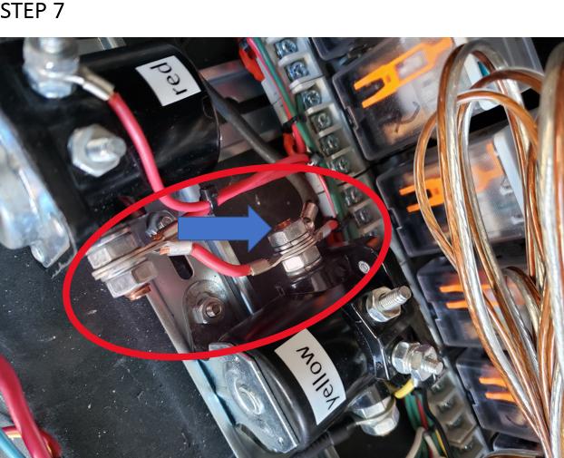 I traced terminal 17 and found that it supplied the power to the center terminals of the solenoids (as indicated inside of the red circle). I determined that the main power wire would work just as well there without any modifications. It proved to be a perfect fit (indicated by the blue arrow).
 The red and the yellow wires split off to two wires on each. I chose the leg I wanted to use and using a mini torch I soldered the terminals on to the wire and covered in shrink wrap.
 I considered trimming off the extra wire but decided to leave it in case it was needed later. I simply cut the end and folded upon itself, covered in shrink wrap and put it back into the bundle.
 Here it is all cleaned up. I taped the wires up and made it all look neat. I got ahead of myself at this point, because I had not yet tested it. Once I was ready, I finally hooked power up, plugged in the pump and solenoid valves and began to test the buttons on the relays. I got the screws on the trunk to rotate both directions and the flipper panel to go up and down and nothing else. The pump would run, but nothing else moved. While carefully watching the hydraulic lines, I noticed the wrong ones were pressuring up. I concluded the pump must be running backwards so I made a quick adapter to change which wire was getting power at the pump plug and depressed the buttons again, it all worked! I found that I needed to swap my yellow and red wires that I attached to the solenoids, but as I said I had already trimmed my wires and didn’t want to have to make patches in the harness.
 I chose a more subtle approach, I swapped the solenoid trigger wires. The red was long enough after I remove a couple of zip ties, but the yellow needed to be a bit longer. I added the extra couple of inches to the back side, so no alterations were needed to an eyelet. I had some additional problems to sort out (with the limit switches) due to equipment being transferred from a donor vehicle. As I stated, making the adjustments to the position of each limit switch was much easier due to being able to test the corresponding relay for each function of the top cycle. The top now functions as well or better than new!
As always, I hope this will help you Thunderbird owners out there! – Kevin Staton = shopguy
Created: January 9, 2021
Last Modified: January 17, 2021
Click HERE: To return to the TRL
Mail: tweetybird"at"squarebirds.org. Replace "at" with @
RETURN TO SQUAREBIRDS.ORG FORUMS