 Tweet
Tweet
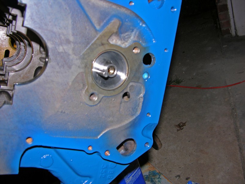
Yes, the locations for the holes in the block are presented by Ford; one is the passenger side lifter oil gallery passage and the other is to the lower drivers' side from the camshaft center, the drilled oil passage to the lower distributor pilot shaft, both welch pluged in the earlier FE's.
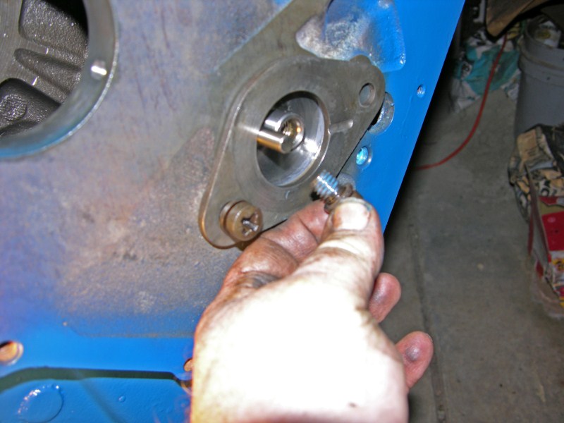
The original thrust-plate retaining fasteners (2) were of 7/16" x 14 thread approx. 5/8" in length w/ lock washer added, w/ modified Fillister style w/ Phillips drive head. Note that adequate tread engagement may not be available for the original fastener due to the relief machined into the face of the block at the galleries to accept the welch plugs.
Also note, if using a non OEM fastener system, pay particular attention for sufficient clearance to timing chain gear!
Scott.


")

Comment