Announcement

Collapse
No announcement yet.

Ignition Problem

Collapse
X
 
  • Time
  • Show
Clear All
new posts
  • jopizz
    Super-Experienced


    • Nov 23 2009
    • 8345

    #16
    Tom,

    Nothing you are telling us from an electrical perspective makes sense. At this point I would totally eliminate the ignition switch and connect the wires one at a time to the yellow wire that has 12V. Here's what you should see.

    Yellow to Red-Green (IGN term)-Voltage at + side of coil
    Yellow to Black-Green (IGN term)-Oil and Gen will light
    Yellow to Black-Green (ACC term)-Fuel gauge should move
    Yellow to Orange-Yellow (ACC term)-Turn signals should work
    Yellow to Black (ACC term)-Heater blower should work
    Yellow to Red-Blue (S term)-Motor should turn over

    If all these tests are positive then there can only be two possibilities. Either the ignition switch is defective or you are connecting the wires to the wrong terminals. Hope this helps.

    John
    John Pizzi - Squarebirds Administrator

    Thunderbird Registry #36223
    jopizz@squarebirds.org 856-779-9695

    https://www.squarebirds.org/picture_gallery/TechnicalResourceLibrary/trl.htm

    Comment

    • simplyconnected
      Administrator
      • May 26 2009
      • 8787

      #17
      A word about voltage testers...
      LEDs and meters are too sensitive, do not draw a load and therefore give false readings at times. (Neon lights are the same.)

      The best voltage testers are the ones you make yourself. Get a good dash light or an 1156, 1157 or just about any 12-volt incandescent light bulb. Either put it in a holder or directly solder two long wires to it (18ga, 18" or 1/2M long), one on the tip and the other on the brass shell. Don't let these wires bridge or touch each other. Tape the metal parts so they are electrically insulated. Alligator clips on the ends work great, especially on the wire you use for ground. The other wire end doesn't matter much because it is only meant for momentary testing. You can strip and solder the end so it won't fray.

      Your new test light should cost nearly nothing but parts from your scrap and spare parts box. Keep it handy for testing blade fuses and all open terminals. I use mine for 'chasing short circuits' that blow car or boat fuses. (You need a load for this and a bulb works perfectly.) I don't let the bulb run long enough to get hot. This test light will give you the truth and great satisfaction as you troubleshoot. - Dave
      Member, Sons of the American Revolution

      CLICK HERE to see my custom hydraulic roller 390 FE build.

      "We've got to pause and ask ourselves: How much clean air do we need?"
      --Lee Iacocca

      From: Royal Oak, Michigan

      Comment

      • tr59bird
        Apprentice
        • Dec 27 2010
        • 54

        #18
        Hi, some updates from testing yesterday:

        When I eliminate the switch and touch the yellow wire from BATT to any of the other wires as John suggested, no voltage is transferred from the yellow wire. In fact all wires (the yellow and any I touch it to) drop to zero volts.

        I was able to confirm the yellow wire from the starter solenoid goes to light switch and there is a jumper from there to BATT terminal on ignition swtich, exactly what Dave said it should be.

        The color of the wires on each terminal don't match up with what Dave said they should be. Following is what I have:

        ACC: one red wire; one brown wire with an in-line fuse; one gang of three wires connected to one molded end (one yellow, one black, one orange)
        IGN: three wires connected via one green molded end (one red, two black)
        BATT: three wires connected via one yellow molded end (one yellow which is jumper from light switch and two green one of which has an in-line fuse)
        ST: one red wire which looks like it has been spliced. It does go to neutral safety switch and I checked continuity between the two.

        I'm starting to think that these wires are so messed that I should just buy the harnesses and replace them all. I really wanted to get to the root of this problem before doing that, but I'm not sure it is possible.

        Thanks,
        Tom

        Comment

        • Joe Johnston
          Super-Experienced
          • Dec 23 2008
          • 720

          #19
          The best voltage testers are the ones you make yourself. Get a good dash light or an 1156, 1157 or just about any 12-volt incandescent light bulb.
          Grew up helping my Dad check things this way, thinking it was only because we were too poor to buy one of those fancy meters! Dad never saw the need, so spending money on something fancy was not considered. I still grab a test light (home made) first and seldom use a meter.

          The second thing I use is a 25' piece of #10 wire with a big alligator clip attached to the battery ground terminal. Guarantees a good ground to whatever is malfunctioning.

          Comment

          • jopizz
            Super-Experienced


            • Nov 23 2009
            • 8345

            #20
            I wouldn't be concerned about the difference in colors. It appears you have a later harness that more closely resembles the 1960 wiring harness. There are also accessories like power windows that aren't on the original diagram that I posted. That's probably the red wire that you see on the ACC terminal. The green wires on your BAT term are for the stop light switch. My main concern is losing your 12V. It's almost like you have no ground. I would check and make sure your negative battery cable is connected tightly to the block and that you have the ground strap from the engine to the firewall. Try running a temporary ground wire from the battery directly to the firewall and see if that makes a difference.

            John
            John Pizzi - Squarebirds Administrator

            Thunderbird Registry #36223
            jopizz@squarebirds.org 856-779-9695

            https://www.squarebirds.org/picture_gallery/TechnicalResourceLibrary/trl.htm

            Comment

            • simplyconnected
              Administrator
              • May 26 2009
              • 8787

              #21
              Originally posted by Joe Johnston
              Grew up helping my Dad check things this way, thinking it was only because we were too poor to buy one of those fancy meters! Dad never saw the need, so spending money on something fancy was not considered. I still grab a test light (home made) first and seldom use a meter.

              The second thing I use is a 25' piece of #10 wire with a big alligator clip attached to the battery ground terminal. Guarantees a good ground to whatever is malfunctioning.
              Joe, your Dad was a very wise man and he taught you well. Many times, "fancy" gets away from "practical". I laugh when I see continuity testers made of metal. The plastic ones are much cheaper, they are insulated and much safer:
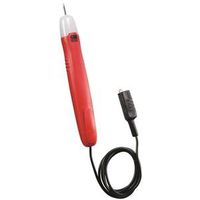
              This one is simply a flashlight bulb, two penlight batteries (in a plastic case), a wire and alligator clip. Nothing works better. If the tested connections have resistance, the bulb shines dim, so you can see how well current flows. If you happen to test a live circuit, the bulb will blow but you won't get shocked.

              Tom, you are missing some important methods in your troubleshooting techniques. GO SLOW and carefully use all your senses. Our frustration is that we rely on your posts to be accurate. All we know is what you tell us so let's straighten your wiring out.

              Every electrical circuit must have two wires for a completed path. John is right in suggesting you double check your ground side because it is equally important as the hot side.

              If your current drops under a load the connections are loose or your battery is dead. <--take this to the bank.

              Start by cleaning the battery posts with a wire brush. Check each connection AND the wires. Give the lugs a good shake. Inspect for corrosion and broken/frayed wires. This should be easy. The yellow wire starts at the Starter Solenoid and the other end terminates at the Headlight Switch. A short jumper feeds the Key Switch. That is three connections, all are UN-fused and they all have nuts for positive, tight clamping.

              Originally posted by tr59bird
              Hi, some updates from testing yesterday:

              When I eliminate the switch and touch the yellow wire from BATT to any of the other wires as John suggested, no voltage is transferred from the yellow wire. In fact all wires (the yellow and any I touch it to) drop to zero volts.

              I was able to confirm the yellow wire from the starter solenoid goes to light switch and there is a jumper from there to BATT terminal on ignition swtich, exactly what Dave said it should be.

              The color of the wires on each terminal don't match up with what Dave said they should be. Following is what I have:

              ACC: one red wire; one brown wire with an in-line fuse; one gang of three wires connected to one molded end (one yellow, one black, one orange)
              IGN: three wires connected via one green molded end (one red, two black)
              BATT: three wires connected via one yellow molded end (one yellow which is jumper from light switch and two green one of which has an in-line fuse)
              ST: one red wire...
              John suggested you have a 1960 wiring harness, which is true. Here is the wiring diagram:


              This is consistent with your descriptions. It is also an upgrade from the '59 harness. It includes in-line fuses and a PINK resistance wire that eliminates the ballast resistor. Otherwise, it works the same.

              Bottom Line: Get your Yellow wire fixed first. It is the most important wire in your whole system. For a load, turn your headlights on. They should shine at full brilliance. - Dave
              Member, Sons of the American Revolution

              CLICK HERE to see my custom hydraulic roller 390 FE build.

              "We've got to pause and ask ourselves: How much clean air do we need?"
              --Lee Iacocca

              From: Royal Oak, Michigan

              Comment

              • tr59bird
                Apprentice
                • Dec 27 2010
                • 54

                #22
                Guys, I finally got some time to work on the bird yesterday. I found a test light I hadn't used in a while but seemed to work fine. I started at the battery testing there and then working my way back to the ign. switch. When I got to the switch I checked voltage at BATT terminal and got a nice bright light. I then put light on IGN - no light: perfect as key is in off position. I then turned the key to on and got generator and oil lights. ***? This car sat in the garage the whole week with no one going in there. I then started the car up with no issues. For next two hours I tried to break it again - cause it to do what it was doing before with the voltage drop. I wiggled wires - anything I could think to do. The only thing different I did when I first started checking things yesterday, other than using the test light, was that I moved the ground wire for the test light to different areas (ground cable from motor to battery, ground at solenoid switch to fender. Used master cylinder for ground when testing yellow wire at firewall) to make sure I got a bright light in all places. I don't know what to say. I'm glad it is working again, but frustrated that I don't know why. At this point, I am going to replace all the wiring due to the condition. As mentioned in my first post I wanted to get to the root of this problem before doing that, but I have lost track of the hours I've spent on this. Does anyone have an opinion on the best place to get the wiring? Macs seems to have most of the wiring I need. Bird's nest has some also and Larry's some.
                I really appreciate the information and help you guys have given me. I learned some about electrical issues going through this but still have a lot to learn. I know it is frustrating for you guys too trying to diagnose with second hand information. Thanks again.
                Tom

                Comment

                • jopizz
                  Super-Experienced


                  • Nov 23 2009
                  • 8345

                  #23
                  Certainly electrical issues can be frustrating. My first thought is loose connections. I usually start at the beginning. Go from the battery and work my way to the solenoid, then the generator, then the voltage regulator, then to the wire connectors next to the master cylinder where they go through the firewall, then to the light switch and then the ignition switch. The fact that nothing worked means that you had a major connection issue. Not just one or two wires. I still think that you have a ground problem that may come back even with a new harness. I would contact Carl Heller(partsetal) and see if he has what you need. He is usually the same price or cheaper than the other vendors. He is much more knowledgeable when it comes to squarebirds and will make sure you get the correct items.

                  John
                  John Pizzi - Squarebirds Administrator

                  Thunderbird Registry #36223
                  jopizz@squarebirds.org 856-779-9695

                  https://www.squarebirds.org/picture_gallery/TechnicalResourceLibrary/trl.htm

                  Comment

                  • simplyconnected
                    Administrator
                    • May 26 2009
                    • 8787

                    #24
                    Do not change your wire harness if there is nothing wrong with it. A new harness will not work any better and you may make wiring mistakes, which makes matters worse.

                    I'm with John. Work on your grounding. New cars have a short #12 green wire starting at the battery NEG terminal and bolted to the body. Another large ground wire connects to the engine (for the starter motor). Follow that same theme.

                    It makes NO sense to ground the water pump when the starter motor is so far away. I ground my engine at the bell housing, close to the starter motor. Use #6 AWG copper stranded wire from Home Depot. Be liberal with your wire because of vibration. Secure it along your engine or along the transmission lines instead of making the end lugs take the brunt of the flexing.

                    I can always tell a good plumbing or electrical job by how well everything is secured. - Dave
                    Member, Sons of the American Revolution

                    CLICK HERE to see my custom hydraulic roller 390 FE build.

                    "We've got to pause and ask ourselves: How much clean air do we need?"
                    --Lee Iacocca

                    From: Royal Oak, Michigan

                    Comment

                    • Astrowing
                      Experienced
                      • Jul 22 2009
                      • 478

                      #25
                      I get a lot of oxidation on my negative battery post which can cause the symptoms you are seeing. Wire brush the posts and terminals and use dielectric grease.

                      I'm an Electrical Engineer and I can't tell ya'll how many times a problem I've had has been due to a bad or floating ground. It can manifest itself as lots of noise in a video circuit or data cable or something that works one day in one location and not the next. With the battery out of the circuit, we use an ohmmeter that can measure low ohms for measuring resistance of wires or cables. Good advice here.
                      sigpic

                      CLICK HERE for Jim's web site

                      Comment

                      • tr59bird
                        Apprentice
                        • Dec 27 2010
                        • 54

                        #26
                        Hey guys,
                        I haven't had any further problems, but in trying to figure out what might have caused the problem, I was checking out other threads in this forum and thought maybe I should confirm my grounding set up is correct.
                        The battery ground is a 1 gauge cable going from batt to the front most bolt on the intake manifold (under the oil filler).
                        The engine to body ground is a 10 gauge (copper) wire going from back of right hand head to the inner fender.
                        Would appreciate if these are correct or if the need to be changed. All wire, cable, and connections are new and securely tightened.
                        Thanks for any info.
                        Tom

                        Comment

                        • simplyconnected
                          Administrator
                          • May 26 2009
                          • 8787

                          #27
                          Tom, a #1AWG is big enough for any system. It's so big, I doubt if it matters where it's connected to your engine but if you want the least resistance for your starter motor (by far the highest load), make your connection as close to it as practical.

                          #10 is good for the body ground. That way the return ground from your headlights and tail lights don't need to go through the engine. Electricity always takes the path of least resistance. - Dave
                          Member, Sons of the American Revolution

                          CLICK HERE to see my custom hydraulic roller 390 FE build.

                          "We've got to pause and ask ourselves: How much clean air do we need?"
                          --Lee Iacocca

                          From: Royal Oak, Michigan

                          Comment

                          Working...
                          😀
                          🥰
                          🤢
                          😎
                          😡
                          👍
                          👎