-
-
Anders, my only Thunderbird sits ontop a trophy. (Thank You very much.)
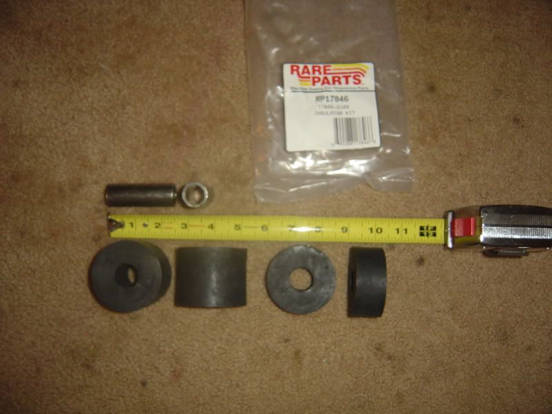
But allow me to draw your attention to this part number again:
It indicates THREE of your bolts are the exact same part number on each side. Ken's attached picture verifies their exact locations. So, all SIX bolts (three on each side) are interchangeable unless someone has changed all six bolts. - DaveMember, Sons of the American Revolution
CLICK HERE to see my custom hydraulic roller 390 FE build.
"We've got to pause and ask ourselves: How much clean air do we need?"
--Lee Iacocca
From: Royal Oak, MichiganComment
-
Anders,
Realising that the bolt is used in three places and from your conversation, I'd agree that the bolt is nothing special and original. That your spacer is shorter than the combined length of the bushings would indicate that the suspension travel shouldn't bind unless the spacer is still too long once it's compressed and carrying a load. I drew a scaled cross section with a 2.5" long spacer as found in the photos and the 1" and 2" bushing without being compressed. Probably of no help, it's attached just in case. Was hoping to help you solve this without having an original piece to measure. Good Luck!Ken
1959 J Convertible
1960 J HardtopComment
-
Comment
-
I've been following along but staying out of this because I don't have any first have knowledge of the 58 rear suspension. After looking at the pictures and Ken's drawings there's one thing I think I can conclude. When those bushings, or 'isolators' are used with a center sleeve, the nut is tightened all the way and torqued to keep it from backing off, there are no 'voids'. the isolators will allow movement when the weight of the car forces them to move, those arms should be HARD to move around by hand. We now know the sizes of the isolators and the bolt. the isolators must get squeezed somewhat to do their job. some pictures of the axle and lower arms/brackets would help me visualize the set up. That's my idea anyway, good luck, Bob CComment
-
Anders, don't cut your spacer. I'm sure it's the correct length. I also agree with Bob C, because with EVERY suspension bushing Ford uses, the inner steel sleeve is torqued tight, and nothing ever pivots on the bolt. BTW, this 5/8" bolt is serious business. It requires a wrench of nearly one inch, with a very long handle.
If your rubber bushings are 3" and the steel spacer is 2-3/4", that only squeezes 1/4" plus the thickness of the lower arm. These bushings are not designed to move or slide under normal driving, otherwise they would erode away in the first year of service causing a terrible noise. The worst these rubber buscuits can do is crack, shrink, and get sloppy.
They are probably not the cause of a hard ride, either. Old springs get too stiff to bounce, worn shocks don't dampen, worn-through bushings cause slop, and old tires are never as smooth as new ones. All these factors constitute the feel of your rear suspension.
Restore the pivot (urethane) bushings and I can't say enough good things about new springs, shocks, and tires. Then, you will have a smooth ride. - Dave
CLICK HERE to see my custom hydraulic roller 390 FE build.
"We've got to pause and ask ourselves: How much clean air do we need?"
--Lee Iacocca
From: Royal Oak, MichiganComment
-
I might not cut the spacers, but something here is wrong.
If I torque it tight, it will limit the whole rear axle movement. The whole travel of the rear axle, going up and down. What happend then is that the forces, created by the weigth of the whole car, will transport through the upper control arm and start breaking the bolt that holds the control arm in the frame/chassie. And that is what have happend in the past, as there is a pivot on the axle housing. Tighteen the spacer, and there is no movement for this pivot.
I have the whole thing set up in the car at the moment, as my rear axle is without the diff, driveshafts and tires. It´s therefor light, and the springs are not there at the moment, so I can move everything I want in order to see how it line up, and runs up & down.
I will try to make a sketch on Monday to describe the "total movement". Or maybe take some pics tomorrow ( I need some assistance in order to hold the rear axle in different positions and be able to take pictures at the same time )
Last edited by Anders; March 5, 2011, 08:36 PM.
)
Last edited by Anders; March 5, 2011, 08:36 PM.Comment
-
Let me think this out...
This whole rear end is a parallelogram. Basically a box with one side fixed to the frame,
and the other three sides hanging with the springs pushing the axle down.

The fixed frame is one side of the box. If you draw a line from A to C (or F to H) pivot points,
that represents the stationary side of the box.
Because the lower arms are so much longer than the top rods (these arms are two sides of
the box), the axle will be allowed to roll to compensate for the difference in swing radii.
The last side of the box is the portion the axle is bolted to; draw a line from B to D (or I to G)
pivot points.
WOOPS! I see what you mean, Anders. Drawing that bolt tight will make the axle and bottom swing
arm one peice. That would stop the axle from rolling. They need to pivot independently. Maybe Ford
tried to lighten the load on the bottom bushing (B) with that rubber. You would be better off with no
rubber in the back. What idiot came up with this design... and Ford used it for a whole model year?
Anders, try running without the bolt and rubbers. I don't see where they actually do any good for your
suspension.
The very top bar is a panhard rod (E to J).

Doesn't make much sense to connect the bottom arm in three places.
If someone sees this differently, please let me know. What a dumb design... - Dave
CLICK HERE to see my custom hydraulic roller 390 FE build.
"We've got to pause and ask ourselves: How much clean air do we need?"
--Lee Iacocca
From: Royal Oak, MichiganComment
-
He,he,he..
I think the first mistake they did, was to not make it parallel. It took me a while to figure out why my upper control arm was either to short or to long (?). The hole for the bolt that holds the front part of the Control Arm ( C & H in your drawing ) have a welded bolt inside that "helpframe", and the only way to reach that one was to cut up the bowl that hold the coil spring . Very tight I tell you. Even more to be able to weld in there...I did it this winter, as one have gone loose due to the forces and I have velded it all together again. But I can also see that a previous owner have welded bigger washers on the outside of booth sides, indicating there have been issues in the past as well. So the forces on this area is very strong.
I first did the same conclusion that you did by proposing to my friends who helped me here last friday, to just ignore the rubber, but we found out that it would most probably give us a "jumpy " rear axle during acceleration or heavy braking. So in the end, we agreed that the isolators ( rubber ) must have been much softer 50 years ago. This is why I also are interested in the original lenght of the sleeve/spacer, as that part is a decider for one of the directions if the rubber compress to its leight.
Yeah, it´s a funny design. Or as one of my friends say: No wonder some people change to leaf springs on these cars.... Last edited by Anders; March 6, 2011, 01:42 AM.
Comment
-
Try it, Anders. I don't think you will find any difference without the rubber because good shocks should take care of any wheel hop. Shorter arms cause the axle to roll more, like your front suspension. There, your bottom arms are MUCH longer than the top "A" arms.
If you had a hotter engine I would suggest leaf springs. After all, you are welding on the sub-frame anyway... might as well weld some perches in and be done with it. New leaf spring sets are US$200.00 here.
Another more difficult but solid option is to retrofit a Fox Mustang 8.8 axle setup. The Fox models used a very stiff back seat plate (#3 crossmember) that Ford welded perches to for the control arms. Mustang GT's used four shocks. Two were horizontal, called 'quarter shocks'.
I still think I would use leaf springs with your axle. They work just fine and are cheap.. I highly doubt that Ford engineered your independent rear setup. I gotta believe Ford bought that change from Budd. I have never seen a more shabby design. - Dave
CLICK HERE to see my custom hydraulic roller 390 FE build.
"We've got to pause and ask ourselves: How much clean air do we need?"
--Lee Iacocca
From: Royal Oak, MichiganComment
-
And all I wanted to know was the length of the sleeves.....
I mean, the original stuff worked on this car ( pic ). That look soft and nice Last edited by Anders; March 6, 2011, 04:37 AM.
Comment
-
I'm still not seeing the way the axle housing is being attached to the lower arms, well not clearly anyhow Looking at the general set-up, other than being a little busy it should be fine. There's two lower arms that pivot in front, the axle should be allowed to roll a little but that's controlled by the two top links. The 'magic' seems to be in the rear bushing/sleeve set-up, and the bushing/bolt that comes up through the square hole. I'm guessing that's where the roll comes in?
Comment
-
Correct. But there is nothing that come up in the "square hole". Just above, in dotted lines, is the rear axle itself. All these things are the same piece.
But the million dollar questions are: How long is the original sleeve/spacer/bushing and how soft is the original Isolator/rubber?
There must be someone 40 miles east of Wixom who still knows this?.....
Last edited by Anders; March 6, 2011, 09:00 AM.Comment
-
Yes, I have someone in mind but He may be somewhere warmer for the winter. I'll make a call and see if I can talk to him. I think I can tell how everything goes together now, tell me again which bolts were breaking? How are the bushings in the front end of the lower arm? Hey, it's only nuts and bolts, right
Comment
-
Actually, it was not the bolt that breaked but where the bolt get into and through the subframe from the front position of the upper control arm into a welded bolt on the inside. One of these bolts welds broke as well. Fixed now. If the bolt ( in the rear that holds the isolators ) is too tight, the control arm is too long, meaning it stressed the most forward point of the control arm ( there is a hughe C in the drawing a few post down ).
All bushings works just perfect.
I have also fixed brand new bushings in the control arm as well. Have them custom made by a shop that do stuff like this on a professional basis. Luckely just like 3 minutes from my home
Last edited by Anders; March 6, 2011, 01:09 PM.Comment
 Tweet
Tweet


Comment