Announcement

Collapse
No announcement yet.

Power Seat Wiring

Collapse
X
 
  • Time
  • Show
Clear All
new posts
  • kevin_tbird
    Experienced
    • Jun 12 2011
    • 157

    Power Seat Wiring

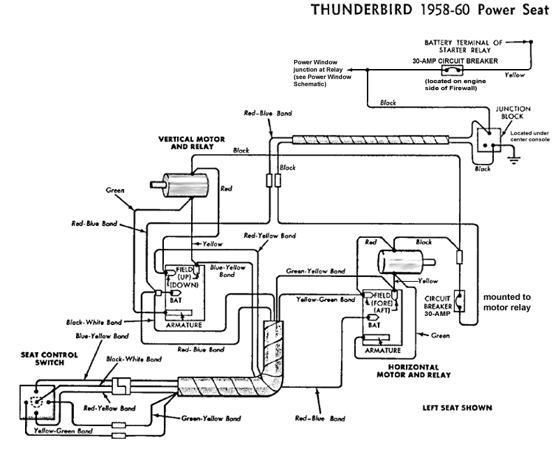
    My early 60 has a power driver's seat. There is a black wire and a red/blue wire running to the seat area. I am assuming the black is a ground wire.

    I have 12+v between the red/blue and the body, but not between the red/blue and black wires. I have very high resistance, multiple mega-ohms, between the black wire and the body.

    Where does the other end of this black wire reside? I am having problems decoding the wiring diagrams that I have and I want to check continuity. I am open to advice here. Note: I have power windows too.

    Thanks, Kevin
  • Dan Leavens
    Moderator / Administrator


    • Oct 4 2006
    • 6377

    #2
    Hey Kev have you tried the Technical pages for the wiring diagram?? Ray loaded them up for us to view and while I am not sure the diagram of the power seat is there it's a good place to start.
    Dano Calgary,Alberta Canada
    Thunderbird Registry
    58HT #33317
    60 HT (Sold )

    Comment

    • kevin_tbird
      Experienced
      • Jun 12 2011
      • 157

      #3
      Dave - thanks for the extra set of diagrams. With the power windows the note says the junction is at the relay. Based on the electrical assembly diagram I've wired the junction as shown in the picture. I have continuity to ground on the black wire, 12v+ on the yellow. Do I have this wired properly? I'd like to isolate the problem before removing the center console to look for any other junction block.

      Thanks,
      Kevin
      Attached Files

      Comment

      • simplyconnected
        Administrator
        • May 26 2009
        • 8787

        #4
        Kev, the yellow and black wires are at the very beginning of this branch circuit.
        I like your photo, but it shows real rusty posts on the CB. Rust is the #1 culprit when it comes to electrical insulation (even in the body panels and spot welds).

        To directly answer your question, YES. That looks very good. Now, keep checking the black wires all the way to your motors. The ground side (or neg) is equally as important as the power side. You're doing well, just keep going.

        Ford changed power wire colors as they passed through connectors. It starts as yellow, continues as Red/Blue, and Black/White. Use these power wires to check for voltage (+12) all the way to your 'joystick' switch and to your motor relays. If you have interruption, either a CB is open or a bullet connector isn't making proper contact. Sometimes all that is necessary is to re-seat connections.

        You don't need to tear the console apart if your motors show power and ground.

        I'm glad to see you are using continuity checks as well as voltage checks. - Dave

        EDIT: Wait a minute, I gotta back up on my prior statement. You should not have a black wire on your circuit breaker. You should have a Yellow wire going in and a Yellow wire going out. The lug going to the relay supplies protected +12 to your power window relay. The Black wire should be connected to your junction block (to chassis ground), not to power. I don't see a junction block in the picture, just a circuit breaker and a relay box.
        Last edited by simplyconnected; October 11, 2011, 03:58 PM.
        Member, Sons of the American Revolution

        CLICK HERE to see my custom hydraulic roller 390 FE build.

        "We've got to pause and ask ourselves: How much clean air do we need?"
        --Lee Iacocca

        From: Royal Oak, Michigan

        Comment

        • kevin_tbird
          Experienced
          • Jun 12 2011
          • 157

          #5
          Now we are looking at the same problem!!!

          My electrical equipment installation manual (page 55) shows the electric seat and window wiring for a 63A vehicle. Wire harness 14643C has three wires running back to the firewall connected to the two outside posts of the relay and one to the circuit breaker. Page #51 calls out two of the wire colors red and red/blue connected to the outside posts of the relay (left & right respectively).

          The third wire in my wire harness is black - and being the only wire left it is the one attached to the circuit breaker.

          [Small side trip. The wire harnesses are all new reproductions. They matched up perfectly with the originals from the car. The seats are out of the car and I was testing the two leads to the seat for voltage when I found a "ground problem" leading to this post.]

          I have 12v+ at the seat. The ground is NOT right. I would think the ground wire would connect to the frame somewhere. The wiring diagram (a couple of posts back in this thread) calls out that the "junction is at the window relay".

          I suspect that the black wire should connect to the base of the relay where it screws into the firewall. But that is not what the diagrams and schematics show.

          AAAgh!!

          Comment

          • simplyconnected
            Administrator
            • May 26 2009
            • 8787

            #6
            Alright, now we're getting somewhere. Yellow should feed the CB, and the other end of that CB feeds the relay contact. Read the note carefully. It says, "On Power Window units junction at WINDOW RELAY." It shows a black dot which means it is a connection point, and it does not say, JUNCTION BLOCK. I don't know, but I would imagine the Junction Block would be at the firewall as a bulkhead that you plug bullet connectors into.

            These diagrams show window motor Black going to a CB, but NOT this power CB. The diagram shows a 30-amp CB with one end already attached to ground. There is also a 15-amp CB there. It looks like these circuit breakers are in the LH cowl side, just before the wire harness enters the driver's door. Every window motor shows its own CB, but the seat motors use one common CB.

            Your harness is primarily for Power Window power and control. I guess we can't talk about the Power Seats without also talking about Power Windows because they use the same power feed. Consider the following diagram and notice that your color scheme is there.
            * Red comes from the IGNITION SWITCH to energize the relay coil and it should be a skinny wire (#16-AWG). This should be the only wire on this relay post.
            The other wires should be heavy (at least #12-AWG).
            * Red/Blue comes from switched relay power. It turns on when you turn the key. This wire feeds BOTH your windows and your seat.
            * Black should go to ground.


            Pull the Black wire off of power. Then, ring it to verify it really does go to all the Black wire locations (at the motors). If it really is the Black wire, connect it to your chassis. - Dave
            Member, Sons of the American Revolution

            CLICK HERE to see my custom hydraulic roller 390 FE build.

            "We've got to pause and ask ourselves: How much clean air do we need?"
            --Lee Iacocca

            From: Royal Oak, Michigan

            Comment

            • kevin_tbird
              Experienced
              • Jun 12 2011
              • 157

              #7
              The black wire at the relay junction does NOT have continuity to ground when I disconnect it from the circuit breaker post.

              The black wire at the seat [ again the seats are out so I am only dealing with the red/blue and black bullet connectors at the seat area] shows resistance to ground which builds and then it snaps to open. I'm guessing it is connected to a circuit breaker somewhere under the dash. I'll crawl under there tomorrow and see if I can trace both black wires.


              edit #1: All power windows get juice. That part of the circuit seems okay.

              edit #2: The 30 amp circuit breaker in the seat diagram is mounted to one of the relays on the power seat motors.

              Kevin
              Last edited by kevin_tbird; October 13, 2011, 08:50 PM.

              Comment

              • kevin_tbird
                Experienced
                • Jun 12 2011
                • 157

                #8
                Okay. I now have power and ground to the power seat.

                The black wire is properly connected to the circuit breaker. It runs through the firewall to a junction block located under the center console. At the junction block it becomes the red/blue wire to the power seats. The black wire to the seat is attached to the mounting screw of the junction block.

                The power window 12v+ comes from the relay. The power seat 12v+ from the circuit breaker.

                The strange thing is I had it wired this way all along. I must have had a wire pinched by the center console somehow, because as soon as the console was off everything worked properly.

                The [bad] picture below shows the junction box location.
                Attached Files

                Comment

                • simplyconnected
                  Administrator
                  • May 26 2009
                  • 8787

                  #9
                  Kevin, thanks for tracking down this mess. Sometimes our prints show wrong (or no) wire colors. From your investigation and findings, I will correct our prints for the benefit of all our members. Your perseverance and tenacity really cleared up many questions.

                  Push F5 (windows screen reset) on your computer and again, look at the Power Seat Diagram and the changes I have made. If we need any further changes, let me know and I will promptly oblige.

                  What bothers me is that the Junction Block has two BLACK wires that do not connect together:
                  One comes from the CB (+12)
                  One is screwed to chassis (NEG)

                  I realize this is Ford's doing. Another practice I'm not happy with is how Ford puts circuit breakers on the NEG side of motor leads. They don't do it on modern cars.

                  Kev, I have one request... could you take a better picture of the junction block under the console? Post it, and I will save all the prints and pictures together, for the power seats and how they tie in with the power windows. Thank You, again. - Dave
                  Member, Sons of the American Revolution

                  CLICK HERE to see my custom hydraulic roller 390 FE build.

                  "We've got to pause and ask ourselves: How much clean air do we need?"
                  --Lee Iacocca

                  From: Royal Oak, Michigan

                  Comment

                  • kevin_tbird
                    Experienced
                    • Jun 12 2011
                    • 157

                    #10
                    Dave - The schematics now reflect what I have on my car and what I believe is stock. The console is all back together - next time I have it off I'll take a better picture.

                    Comment

                    Working...
                    😀
                    🥰
                    🤢
                    😎
                    😡
                    👍
                    👎