1960 SQUAREBIRDS POWER WINDOW MOTORS
BY: 60 T-Bird (Martin Burs) & Simplyconnected
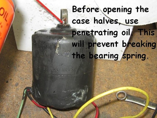
This Power Window Motor is from a 1960 Thunderbird. There are slight
internal differences between this, and the 1958 and 1959 Squarebird motors.
Picture #1 The two long mounting screws were removed for easy
wheel access. Before attempting disassembly, BE SURE there are no dents or
raised metal (dings) on the motor shaft.
If there is, the shaft will hang up on the bearing, causing unnecessary damage.
Use a fine file and go over the shaft surface. Any imperfections will show
up immediately. File them smooth. The housing shell should easily
slide off of the motor shaft.
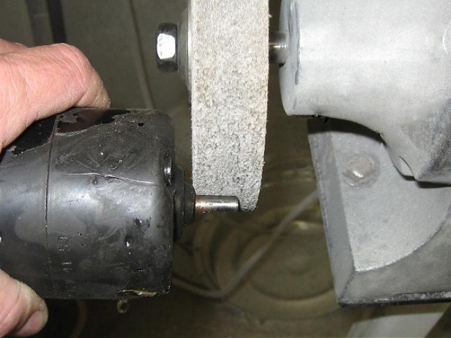
Picture #2 This is a ScotchBrite wheel,
not a grinding stone! The purpose is to remove paint, rust, and scale,
not dents or dings.
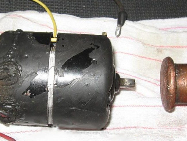
Picture #3 File the set screw marks so they aren't raised
and gently tap the bearing off. If you feel resistance, look for an
obstruction on the motor shaft. Continued hammering will destroy the
bearing.
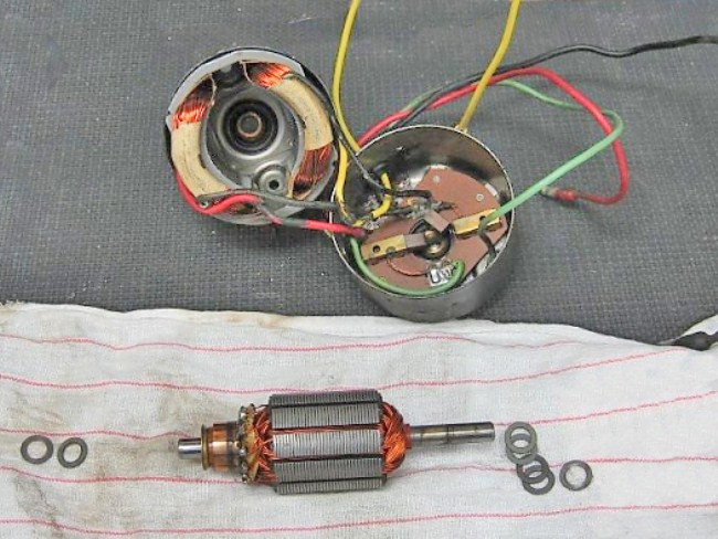
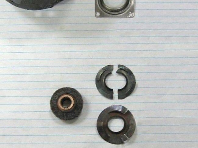
Picture #4 Here are the parts laid out.
Keep track of the washers as they control end play and center the armature in
the housing.
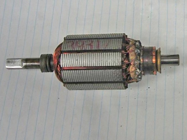
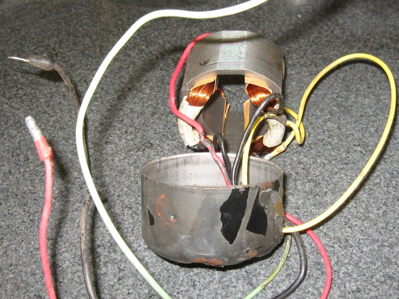
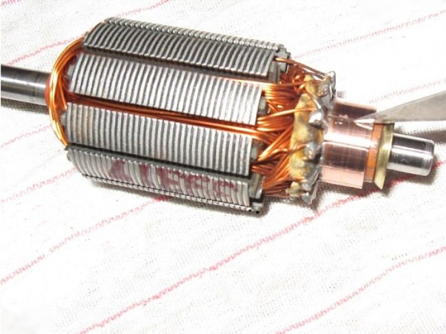
Picture #5 This is the armature before the commutator segments are cleaned-up.
This commutator shows evidence of excessive oil or grease, but a careful
inspection shows no burned, scored, or tapered segments.
* Commutator segments are made of soft copper with micarta between them. The
brushes are made of carbon-impregnated bronze. This combination serves
many purposes: The materials are heat resistant (lots of current to causes
arcing), the carbon forms a lubricating surface that current easily passes
through, and they last many decades.
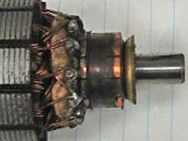
Picture #6 Cleaning is all that is necessary here. As a
LAST resort, a commutator can be 'trued' by tooling the copper down on a lathe,
but the protective surface will be gone and the micarta will need to be undercut
with a knife. Then, the brushes should be arced to match the new
commutator radius. Further 'break-in' will sacrifice some brush length.
Picture #6 C.
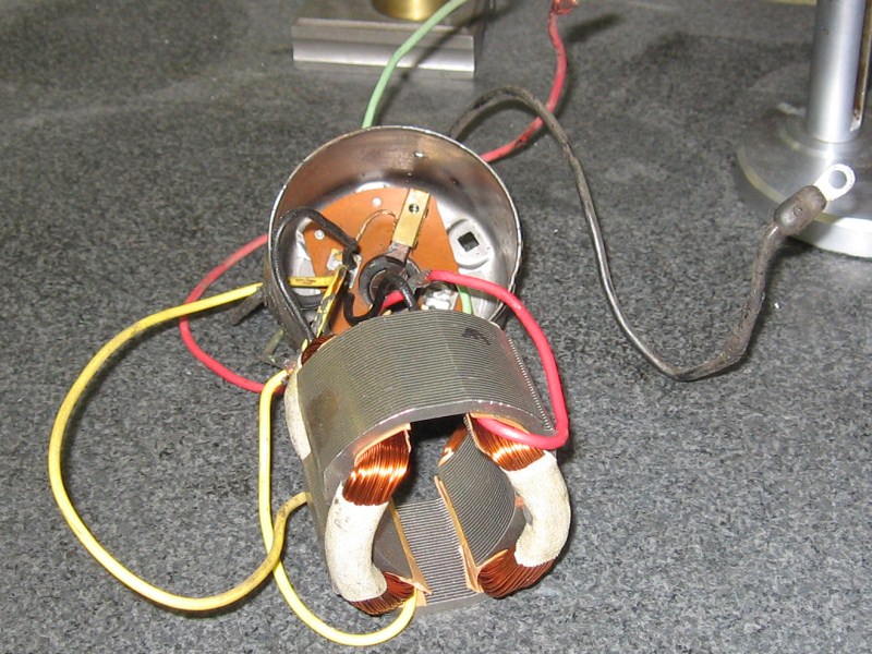
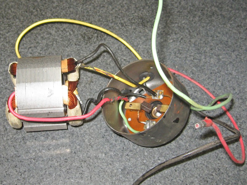
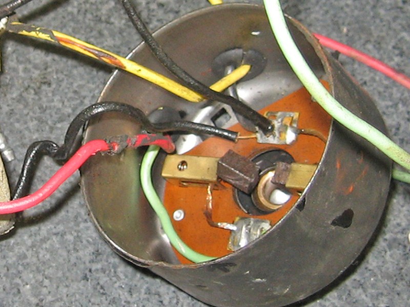
Picture #9 This is an excellent image showing the brush
holders and where the wires are soldered. Ford kept the integrity of using
Black for all ground wires.
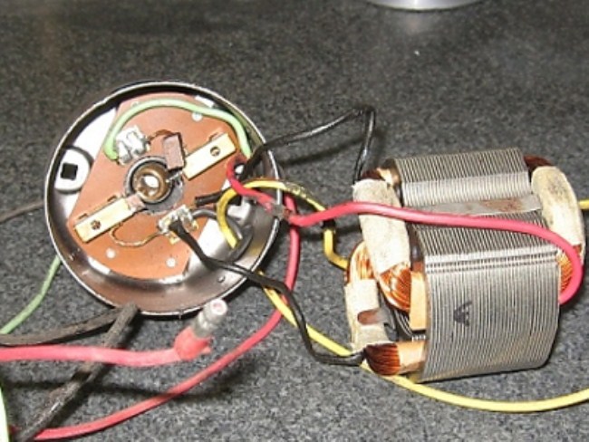
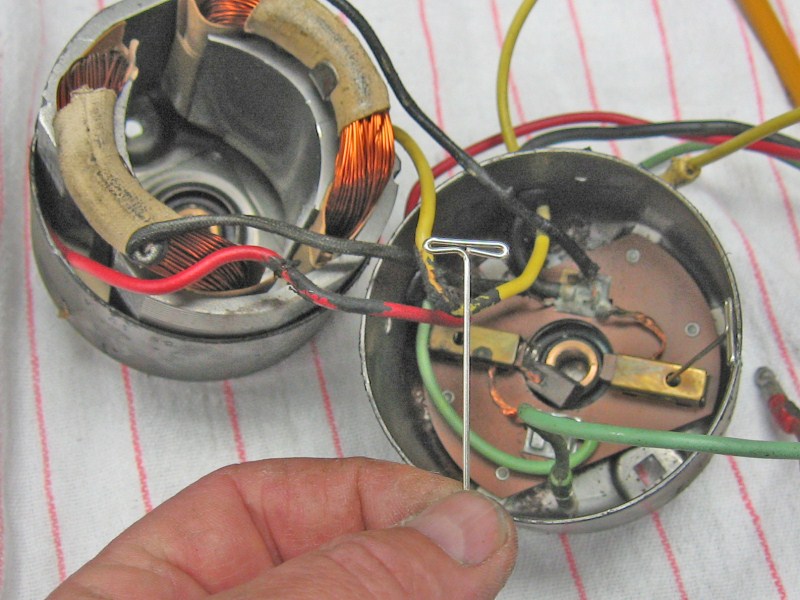
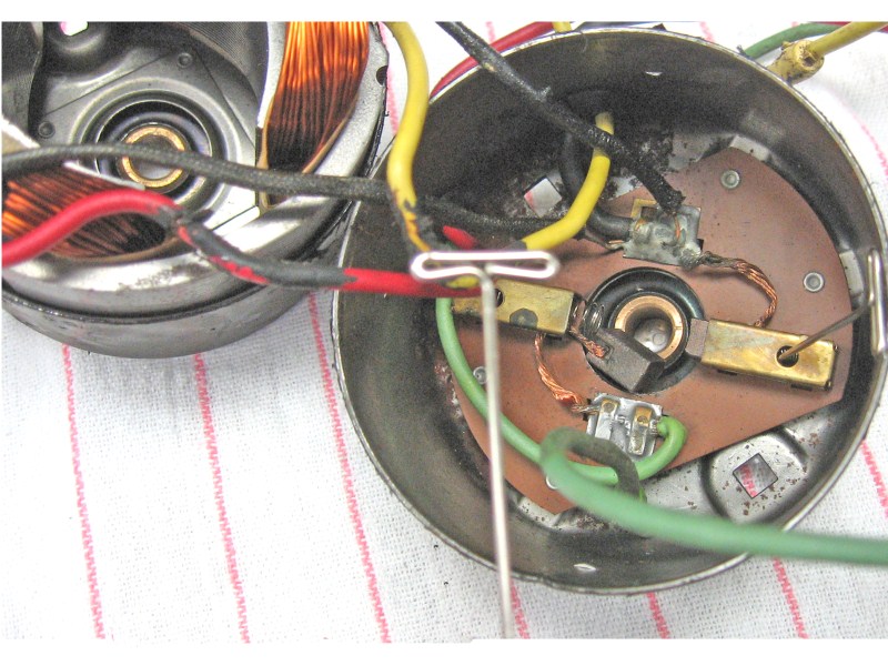
Picture #9 This image shows the sintered oil
lite bearing (on the left) with a surrounding felt oil retainer. The
reason it is out of the holder (top) is because the motor shaft had a bur and
further hammering destroyed the rivets and the spring washer. The
replacement spring is on the bottom right.
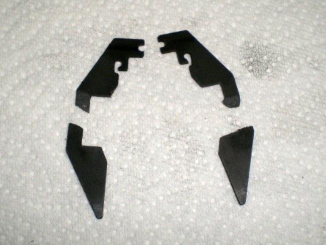
Picture #10 This is a broken brush holder from
a pre-1960 motor. Epoxy was used to repair it.
Here is an end view of the switch and contacts. All of the contact plates were
bent down at the corners. I used two needlenose pliers to straighten them out.
Next remove the contact plate retainer and spring.
Just pry out on one side and the retainer and spring will come out. I bent the
sides of the spring retainer in a little to insure a good fit on reassembly.
Remove the spring from the retainer and stretch it out. It can be done by hand
but they're tough little buggers and unless you've got the Vulcan death grip
down, pliers might be easier. I found this step to be necessary after testing on
the first switch I did. It takes a lot of play out of the switch and prevents
the contacts from sticking, i.e. power staying on when switch is released.
In the assembled picture with the contacts on either side, they should be
straight across or bent slightly upward. They can be bent with your fingers
pulling up from both sides across the top of the spring retainer. I put a small
amount of dialectric silicone grease on all the contacts before assembly.
Time for reassembly.
Make sure the switch and switch housing are properly oriented. The white plastic
toggles should all have the angled surface pointing toward the outer edge of the
four switch housing and the side with the holes toward the center. Insert switch
in housing and install the small clip first. Hold down on the switch and push
the clip in with a small screwdriver until you hear it click into place. Now
insert the outer clip and push it in until it clicks. I bent the outer clips
outward a little to insure a snug fit in the console. This will also hold the
switches tighter in the switch housing. Before reinstalling in the car I tested
the switch function with an ohmmeter. O.K., all back together! Have a libation
of choice and watch the windows go up and down. Mike
Time for reassembly.
Time for reassembly.
Time for reassembly.
Created: 15 July, 2009
Last Edited: 31 July, 20109
Email: webmaster@squarebirds.org
Return to Squarebirds Home.